A motor burns out six months after installation. A control panel behaves erratically every time there’s a thunderstorm. Sensitive instrumentation gives inconsistent readings with no apparent cause. In each of these cases, the investigation eventually leads back to the same place: a compromised, incomplete, or entirely absent earthing system.
Earthing protection is discussed predominantly in terms of personal safety, and rightly so. But its role in protecting equipment is just as critical, and considerably less understood. The reality is that a properly designed electrical grounding system doesn’t just protect people from shock. It actively shields every piece of equipment connected to that installation from a range of electrical threats that would otherwise cause slow degradation, sudden failure, or irreversible damage.
Understanding how earthing achieves this, and what happens when it doesn’t, changes how you think about every electrical installation you design, specify, or maintain.
What Earthing Actually Does to the Electrical System
Most explanations of earthing stop at “it provides a path to ground for fault current.” That’s accurate but incomplete. Earthing does something more fundamental: it establishes a stable voltage reference for the entire electrical system.
Every piece of equipment in an installation operates relative to Earth’s potential. When that reference is solid and consistent, equipment sees exactly the voltages it was designed to handle. When earthing is weak or absent, that reference drifts, and equipment starts operating under conditions its designers never accounted for.
Here’s where things get interesting. A floating or high-impedance earth doesn’t just create a shock hazard. It causes voltage instability throughout the system. In digital equipment, this manifests as data errors and processor faults. In motors, it accelerates the breakdown of insulation. In sensitive instruments, it introduces noise that corrupts measurements. The equipment isn’t failing randomly; it’s responding to electrical conditions that earthing protection was meant to prevent.
Earthing doesn’t just give fault current somewhere to go. It gives every voltage in the system a stable point for measurement.
The Four Mechanisms of Equipment Protection
Earthing protects equipment through four distinct mechanisms. Each operates differently, and each addresses a specific category of electrical threat. Understanding them separately makes it much easier to diagnose failures and design protection that actually works.
01. Fault Current Diversion
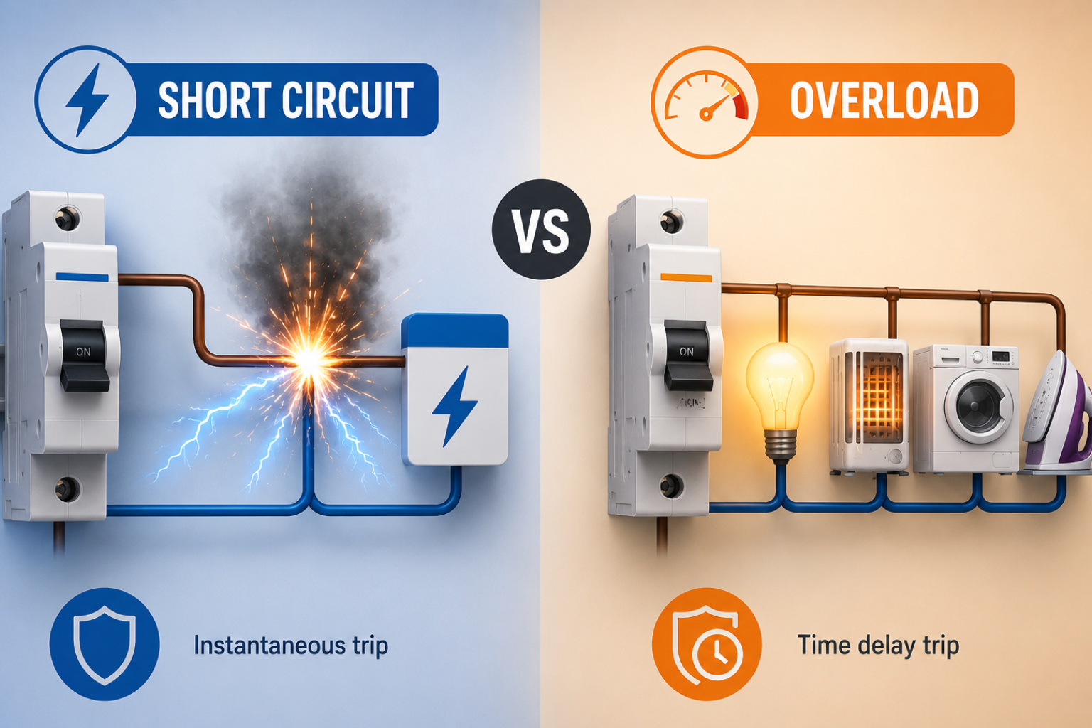
When insulation fails and a live conductor contacts metalwork, the earthing system provides a low-impedance return path. This allows fault current to flow at levels high enough to trip protection devices cleanly, before sustained current can overheat conductors or damage equipment.
02. Voltage Stabilisation
A solid-earth reference prevents the system voltage from floating relative to ground. This directly protects equipment insulation, which is rated for specific voltage-to-earth levels. Without a stable reference, transient overvoltages can appear across insulation that was never designed to handle them.
03. Surge & Transient Dissipation
Voltage surges from lightning, switching events, and grid transients need somewhere to go. A proper electrical grounding system provides that path, directing surge energy into the earth rather than through equipment circuits, where it causes catastrophic damage.
04. Equipotential Bonding
By bonding all exposed metalwork to a common earth reference, earthing eliminates potential differences between adjacent equipment. Without this, fault conditions create voltage gradients across connected equipment, stressing insulation and driving unexpected current through circuits not designed to carry it.
What most people don’t realise is that VFDs and motor drives are particularly sensitive because they generate high-frequency switching currents that actively seek an earth return path. If that path has high impedance, due to an undersized earth conductor or poor connections, those currents find alternative routes through bearings, signal cables, and adjacent equipment. The result looks like a random equipment failure. The cause is always the earthing system.
How Poor Earthing Defeats Protection Devices
This is the relationship that gets overlooked most often. Circuit breakers, RCCBs, and other protection devices all depend on the electrical grounding system to function correctly. They don’t operate in isolation; their entire trip mechanism relies on fault current flowing at detectable levels. And fault current flows only at those levels if the earth-return path has low enough impedance.
Consider what happens during an earth fault when earthing resistance is high. Fault current is limited by that resistance. If the current remains below the protective device’s trip threshold, the breaker or RCCB never operates. The equipment remains energised, exposed to sustained fault current, far more damaging than a clean trip and restart would have been.
Critical Dependency
An MCB or RCCB can only protect equipment if the earthing system allows fault current to reach its trip threshold. High earth resistance directly suppresses that current, and a protection device that cannot trip is no protection at all. Switchgear protection and earthing protection are not separate systems. They are interdependent.
This is why Eurogrid designs its circuit protection products and earthing accessories as a coordinated range. The performance of one depends directly on the quality of the other. An installation that specifies premium switchgear but neglects earthing quality is building on an unstable foundation.
The Surge and Transient Problem
Voltage surges are responsible for a significant proportion of premature equipment failures, and earthing is the first line of defence against them. Every time a large motor starts or stops, every nearby lightning strike, and every switching event on the distribution network generates a transient voltage. These transients are brief but intense, and they travel through the wiring into connected equipment, causing damage along the way.
A proper electrical grounding system provides the low-impedance path these surges need to dissipate safely. When surge protection devices (SPDs) are installed alongside quality earthing accessories, earth rods, earth pits, and bonding conductors, the combination intercepts surges before they reach equipment terminals. When earthing is inadequate, SPDs cannot discharge effectively, and the surge continues into the circuit.
Real-World Scenario
A manufacturing facility experiences repeated failure of PLC input cards following the monsoon season each year. Every card burned in the same way, overvoltage on the 24V signal lines. The culprit: a poorly connected earth pit with seasonal resistance spikes during dry weather, combined with lightning-induced transients on the incoming supply. Once the earthing system was rebuilt with proper earth rods and bonding conductors, and the resistance values were verified, the failures stopped entirely.
The PLCs hadn’t changed. The lightning hadn’t changed. The earthing had.
Ground Loops: The Hidden Equipment Killer in Instrumentation
In industrial facilities with extensive instrumentation, temperature sensors, pressure transmitters, flow meters, and analytical equipment, ground loops are one of the most persistent causes of signal corruption and equipment damage. They’re caused by different earth potentials at different points in a system, driving small but damaging currents through signal cables.
What makes ground loops particularly frustrating is that their effects are intermittent and difficult to trace. Sensors give fluctuating readings. Control systems respond to phantom signals. Equipment that tests fine in isolation behaves erratically when connected to the wider system.
The solution is equipotential bonding, ensuring that all equipment in the instrumentation loop references the same earth potential. This is achieved through careful design of the electrical grounding system, not by adding more individual earth connections. In our experience, adding uncoordinated earths often makes ground-loop problems worse, not better.
What a Good Earthing System Actually Looks Like
Effective earthing protection for equipment isn’t achieved by a single electrode. It’s a system, designed, installed, tested, and maintained as a coherent whole. The components matter, but so does how they work together.
Earth Electrodes and Earth Resistance
The earth electrode, whether a rod, plate, or ring, provides the physical connection between the electrical system and the earth. Earth resistance must be low enough to allow fault current to flow at levels that operate protective devices. For most industrial systems, a resistance below 1 ohm is the design target. For sensitive equipment and critical systems, lower is always better.
Earthing Conductors and Connections
Conductors connecting equipment to the earth electrode must be sized for the maximum fault current they may need to carry, not just for normal operating current. Poor connections and undersized conductors are frequently the point of failure in otherwise adequate earthing designs.
Main Earthing Terminal and Bonding
All protective conductors, bonding conductors, and earth electrode connections should meet at a main earthing terminal. This single reference point ensures the whole system operates at a consistent potential and makes testing and maintenance straightforward.
Periodic Testing
Earth resistance changes over time due to soil moisture, corrosion, and physical disturbance. Testing at commissioning establishes a baseline. Periodic retesting catches degradation before it becomes a safety issue or causes equipment damage. An earthing system that has not been retested since installation is not one you can rely on.
Design Principle
Earthing protection should be designed alongside the electrical system, not added at the end. The decisions made at the design stage about electrode type, bonding paths, and conductor sizing determine how well protection devices perform, how long equipment lasts, and how the system behaves under fault conditions.
Earthing in the Context of an Electrical Installation
It’s worth stepping back to see where earthing sits in the full electrical protection picture. In a well-designed installation, earthing protection is the foundation. Above it sit the protection devices, MCBs, MCCBs, RCCBs, and surge protection devices. Above those sit the equipment and loads the system serves.
Remove or compromise the foundation, and the entire structure above it is weakened. Protection devices that can’t trip, surges that can’t dissipate, fault currents that can’t flow, all of these failures trace back to earthing. The switchgear and protection devices are only as good as the grounding system they depend on.
This is the lens through which Eurogrid approaches its product range. Circuit protection devices, earthing accessories, lightning protection, and industrial switchgear are not independent categories; they are components of a single, coordinated protection system. Each one reinforces the others, and specifying them together from a manufacturer who understands that relationship is itself a form of protection.
Equipment failure is expensive. Downtime is expensive. Investigating the root cause of persistent, unexplained faults is expensive. In most cases, the cost of a properly designed electrical grounding system is a fraction of the cost of any of those consequences, and it prevents all of them simultaneously.
Eurogrid‘s earthing and lightning protection accessories are designed to work within complete electrical systems, providing the reliable, low-impedance earth connection that both equipment protection and switchgear operation depend on. Explore the range, or speak with the Eurogrid team about earthing requirements for your specific application.
Build the Foundation Your System Depends On
Explore Eurogrid‘s earthing accessories, lightning protection, and circuit protection range, designed to work together.
View Earthing & Protection Products